Real Time Synchronization

Introduction

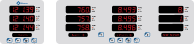
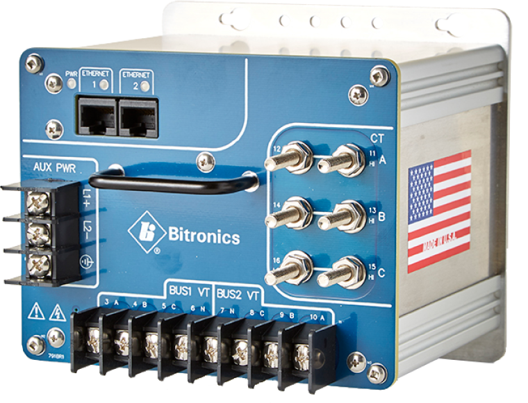
The PowerPlex II (PPX II) is a new Automation Transducer built in the same package as the original PowerPlex, or with digital I/O added, in the M571 case. It is an Ethernet transducer with fast, 1-cycle updates that can be used in SCADA automation schemes and in synchronizing applications in conjunction with PLCs. It is an excellent choice as a replacement for the Bitronics M571 in non-recording applications. Two sets of three-phase voltages that allow direct connect for 600V ac systems are provided.

Communications

No need for PC software – Ethernet service port provides access to web server in the instrument so meters can be interfaced with just a web browser for viewing and configuration.
Ethernet protocol support for DNP3, Modbus TCP, EtherNet/IP or IEC 6185.
Built-in Ethernet switch allows pass-through from one device to another.
An option for both standard secondary “optimal resolution”or primary units makes communications with SCADA/RTU more flexible.
Optional display port and IRIG-B port.
Optional configurable RS-232/RS-485 serial port supports Modbus or DNP3 serial protocols.

Measurements

Full basic measurement & recording set with demand and harmonic values plus phase angle, voltage differential and slip frequency used in synchronizing applications.
0.2% revenue accuracy.
Updates every 1 cycle.
Optional trend recording.

Built for the Substation

Wide-range universal power supply
Rugged aluminum case
Reduce inventory cost as one model covers all wiring options
Easy to mount with compact transducer footprint

Applications

Synchronizing, voltage control, power factor control, and load shedding.
Digital front-end to SCADA systems.
Intelligent Electronic Device (IED) interfacing to RTUs and PLCs.
Plant equipment, line, power & energy monitoring.
Breaker status, rack-in, rack-out in switchgear.
Trend: transformer loads and voltages in E/M relay substations, battery voltage, Total Harmonic Distortion.

Environmental

Operating temperature range -40° to 70°C, storage temperature -40° to 85°C.
Humidity 0-95% non-condensing.
Surge withstand to ANSI/IEEE C37.90.1: 2002.
UL/CSA Recognized, File Number E164178, CE Marked.

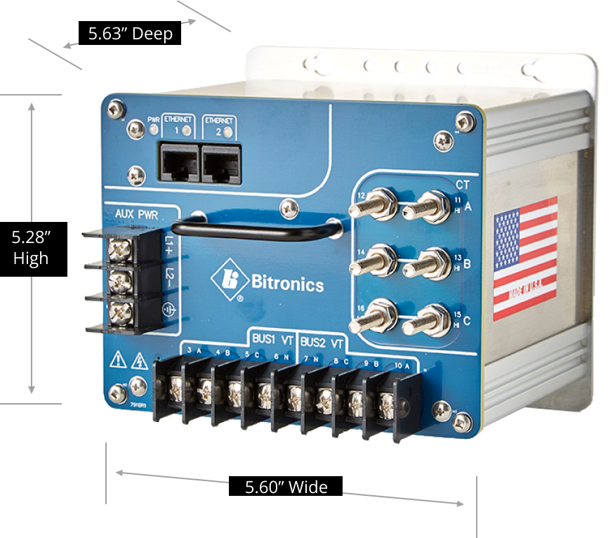
Wide chassis (with I/O and serial port): 5.2” H x 8.5” W x 5.9” D(132mm H x 216mm W x 150mm D).

Specifications

Dimensions

Standard chassis:
5.28” H x 5.60” W x 5.63” D – overall depth including handle is 5.75” D (134mm H x 142mm W x 143mm D – overall depth including handle is 146mm D)
Wide chassis (with I/O and serial port):
5.2” H x 8.5” W x 5.9” D (132mm H x 216mm W x 150mm D)

Weight

Standard chassis
2.3 lbs. (1.04 kg)
Wide chassis (I/O and serial port)
3.5 lbs. (1.59 kg)

Power Supply

12 – 40V dc nominal, intended to connect to 12 and 24V batteries
or 48-250V dc/55-240V ac with builtin monitoring

Current Inputs

5A nominal to maximum of 10A (2x overload)

Voltage Inputs

600V ac nominal, 45-65Hz

Outputs

Outputs Dual RJ45 10BaseT/100BaseTX ports (Ethernet switch) for service port functions, Modbus or DNP3 TCP/IP support; IEC61850 support optional display and IRIG-B ports

Digital Inputs

Optional 4 or 8; High speed, suitable for 1ms SOE
Nominal Input Range
24V dc to 250V dc
Threshold Voltage
15V dc +/-1V or 80V dc +/-5V (at 25C)
Input Resistance
33kohm
Input De-bounce Time
Selectable, from 1 ms to 2 s

Digital Outputs

Optional 4
Tripping duty relay
Resistive: 30A
Continuous Carry: 5A
Break Inductive @48V dc: 700mA
Break Inductive @125V dc: 200mA
Output Operate Time (time from command by Host, does not include protocol delays)
Assert (Close time with “N.O.” jumper): 8ms
Release (Open time with “N.O.” jumper): 3ms

Isolation

I/O Terminals to Case

2000V ac, 1 min
I/O Terminals to Channel
2000V ac, 1 min (channel 4 to other channels)

Available Measurements

Amps A, B, C, Residual
Average 3-Phase Amps
Average 3-Phase Volts (1& 2)
Average Volts, Avg. Max Volts, Avg. Min Volts AN, BN, CN, AB, BC, CA (Bus 1)
Avg. Watts, Avg. Max Watts, Avg. Min Watts A, B, C, Total
Average VARs, Avg. Max VARs, Avg. Min VARs A, B, C, Total
Average VAs, Avg. Max VAs, Avg. Min VAs A, B, C, Total
Class 0 Response Setup
CT Scale Factor/Scale Factor Divisor
Demand Amps, Max Amps A, B, C, Residual
Demand Fundamental Amps, Max Fund. Amps A, B, C, Residual
Displacement Power Factor A, B, C, Total
al x Factory Version Hardware/Software
Frequency (System)
Frequency Volts A, B, C (1 & 2)
Fund. Amps A, B, C, Residual
Fund. Volts AN, BN, CN, AB, BC, CA (1 & 2)
Health
Heartbeat
K-factor Amps A, B, C, Residual
Meter Type
Phase Angle Amps A, B, C
Phase Angle Volts A, B, C; AB, BC, CA
Phase Angle Volts A 1-2, B 1-2, C 1-2
Power Factor A, B, C, Total
Protocol Version
PT Scale Factor/Scale Factor Divisor
Slip Frequency Volts A 1-2, B 1-2, C 1-2
Symmetrical Components Bus 1 & 2 Volts (Magnitude and Angle)
Symmetrical Components Current (Magnitude and Angle)
Tag Register
TDD Amps A, B, C, Residual
TDD Denominator A, B, C
THD Volts AN, BN, CN, AB, BC, CA
Unbalance Amps
Unbalance Volts (1 & 2)
Uncompensated VARs, Total
Uncompensated Watts, Total
VA-Hrs
VAR-Hrs Lag/Lead
VARs A, B, C, Total
VAs A, B, C, Total
Volts AN, BN, CN, AB, BC, CA (1 and 2)
Volts Aux1-Aux2
Watt-Hrs Net/Normal/Reverse
Watts A, B, C, Total

Let’s talk

Call us today at 844.NovaTech (668-2832)

Or please fill out this form and someone will get back to you shortly.