DNP Scaling 101
PUBLISHED ON Jun 28, 2010
Choosing the Right Scaling Factors for Bitronics IEDs
Q: My SCADA software gives me one field to enter a scale factor and a field to enter a zero offset for converting each DNP analog point into primary engineering units. The Bitronics®configuration software asks me to enter a CT scale factor and a VT scale factor, but it doesn’t mention anything about what scaling to use for power, frequency, or other kinds of points besides the current and voltage. How do I choose the best scale factors to enter in the Bitronics software? Then what should I enter in SCADA?
A: The settings for Modbus and DNP scaling on the 70 Series IED are designed to make most analog points work out for an optimum balance between range and resolution if you enter the same value for the CT and VT Scale Factors that you use for the CT and VT ratio settings. That is, if the current and voltage are optimized, then the watts, VArs and VA will also work out. Some measurements, like power factor and frequency do not depend on the CT and VT Scale Factors at all, and are handled a little differently. And some measurements, like line-to-line volts may require you to choose a different value for the VT scaling factor than you use for the VT ratio under certain circumstances.
To keep this from getting confusing, let’s break the answer into three parts. In the first part, I’ll describe the typical case where the scaling factors are the same as the instrument transformer ratios. In the next issue of TechTalk we’ll handle exceptional cases, where you might want to use a Scale Factor that’s different from the transformer ratios. Then in the final part, we’ll describe points where the scaling factor doesn’t have anything to do with the CT and VT ratios. At the conclusion of the three-part series, we’ll concatenate all three parts into a single white paper that covers all scaling issues comprehensively. I’ll even throw in a primer on binary integer math and the significance of “two’s-complement” encoding.
DNP Scaling, Part 1:
The Typical Case
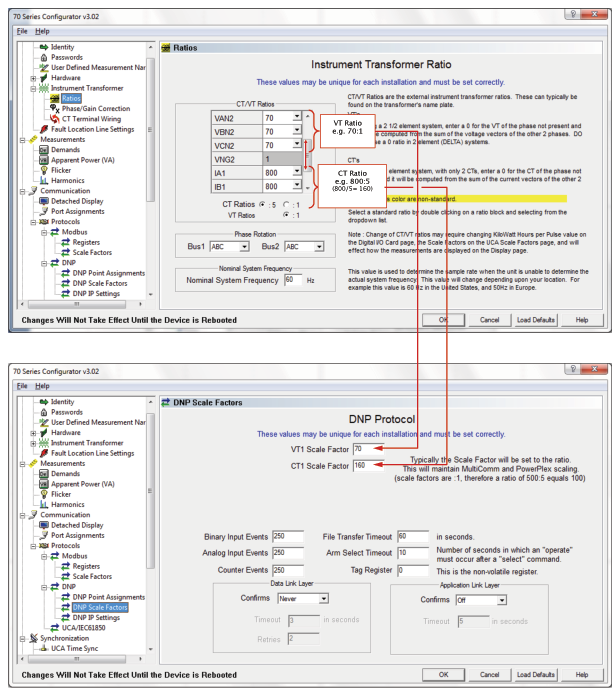
The 70 Series Configurator software has one page (Figure 1, top) to enter the CT and VT ratio settings. There is another page (Figure 1, bottom) for each protocol where the CT and VT Scale Factors are entered. That way Modbus and DNP protocols can be scaled independently. For the IED to work properly, the CT and VT Ratio settings must always be set equal to the actual turns ratios of the instrument transformers connected to the voltage and current terminals of the IED. It is never necessary to “trick the meter” by multiplying a ratio times root-three, or any other value under any circumstances. But the CT and VT Scale Factor settings can be manipulated to adjust the range and the resolution of various measurements according to the unique circumstances that may arise in a substation.
Figure 1
In the typical case, you would enter a CT Scale Factor equal to the CT Ratio setting and the VT Scale Factor equal to the VT Ratio setting. There is an equation on the DNP Points page (Figure 2) that can be used to calculate the scale factor you should use in SCADA.
For most analog points, such as amps, volts, watts and VArs, the equation has the general form:
PEU = RV/32,768 * FSV * SF
Where:
- PEU is the primary engineering units. This is the “answer” you’re generally looking for.
- RV is the raw DNP integer value (“Register Value” shown in figure 2).
- FSV defines the full scale value of the parameter being measured in secondary units. (The “10” shown in the equation in Figure 2 is 10A on the low side of the CTs. That is, 5A full-scale times a transformer rating factor of 2.)
- SF is the scaling factor (the CT Scale Factor in Figure 2).
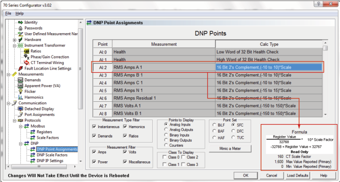
Figure 2
Notice a couple things about the equation shown in Figure 2:
1. The equation is dynamic. That is, the equation changes when you click on different DNP points in the point list above. So the FSVterm may be 10 for current, but 150 for voltage, and 4500 for power. The SF term is the CT scale factor for current, the VT scale factor for voltage, and for power, SF if the CT scale factor times the VT scale factor.
2. Notice the equation is a direct proportion. That is, it takes the form Y = m X. There is no zero offset (such as would be in the form Y = m X + b). So the zero offset (b) is zero, and the scale factor that you enter into SCADA (m) is given by:
m = FSV * SF / 32,768
So, using the term “m” (above) for the SCADA scale factor, the equation in the Configurator program becomes: PEU = RV * m, which is exactly what SCADA expects to see.
3. This equation will produce primary engineering units having the best possible resolution for a scaled 16-bit integer as long as the product of FSV * SF is close to the maximum value you ever expect the engineering units to have.
4. The IED can never produce a measurement higher than FSV * SF, because RV can never be greater than 32,768.
Let’s work an example:
Say you’ve got a typical 13kV distribution substation station. Your PT ratio is 70:1, and your CT ratio is 800:5. The system is connected in a wye. On a particular day the line-neutral voltage is 7,765V and the current is 670A. Let’s say the system is well balanced and the power factor is 0.97 lagging so total watts, P = 15.75MW and total VArs, Q = 3.93MVAr. In SCADA you want to read the line-neutral voltage, the current, watts and VArs. How do you set up the Scale factors in the 70 Series IED and in your SCADA software?
1. On the Ratios page in the 70 Series Configurator program, set the CT ratio to 800 on all three phases making sure the radio button indicates 800 means 800:5 and not 800:1. Set the VT ratio on all three phases to 70. See Figure 1, top.
2. On the DNP Scaling Factors page in the 70 Series Configurator program, set the CT Scale factor to 160 (800/5=160 and the scale factor setting must be reduced). Set the VT scale factor to 70. See Figure 1, bottom.
3. Go to the DNP Points page in the Configurator and click on any of the points that are configured to represent amps (AI:2, 3, or 4 shown in Figure 2). Look at the equation in the lower right corner of the page. The equation tells you that the primary current, I = RV/32768 * 10 * 160. (See how the Scale factor is identified as 160 immediately below the box?) The scale factor to use in SCADA is: 10 * 160 / 32768 = 0.048828. In other words, SCADA polls the IED, which reports point AI:2 is a raw DNP Integer of 13,722. So SCADA needs to multiply 13,722 counts by the scale factor 0.048828 to get 670A. If you prefer, and your SCADA software supports it, you could take the reciprocal of 0.048828 (which is 20.48) and set your SCADA software to divide the raw integer 13,722 by 20.48. You would get the same results, 670A. That’s it for Amps.
4. Volts is similar to Amps with just a couple slight differences. When you click on the point AI:7 in the point list in the Configurator, the equation changes to RV/32768 * 150 * 70, where 150 is FSV and 70 is the VT scale factor. You calculate your SCADA scale factor as 150 * 70 / 32768 = 0.320435. Now when SCADA reads the IED, it reports AI:7 is 24,233 counts. When SCADA multiplies 24,233 by 0.320435, you calculate the voltage as 7,767V which is right, but you probably prefer SCADA to display voltage in terms of kV. To do that just requires you divide the SCADA scale factor for voltage by 1000. So the scale factor becomes 0.000320. Again, it is probably more convenient to take the reciprocal of the scale factor and set up SCADA to divide the raw DNP integer by 3,120.76 rather than to multiply by such a very small number.
5. The SCADA scale factors used for the Watts and VArs are both the same. In this case, the equation in the Configurator changes the FSV to 4500 and the scale factor is now the product of the CT scale factor times the VT scale factor. When you’ve done that, the engineering units will be presented in terms of watts, and you probably prefer SCADA to read in terms of MW, so you will have to divide the scale factor that you calculate by one million, just as we divided the scale factor for voltage by 1000 to get it to be expressed in terms of kV in number 4, above. For Watts, refer to Figure 3.
Clicking on point AI:24 in the Configurator makes the equation change to: RV/32,768 * 4,500 * 11,200(because 11,200 = 70 * 160.) So the scaling factor you use for SCADA is 4,500 * 11,200 / 32,768 which is 1,538.09. You want the result in MW, so next divide that by one million to get 0.001538. That’s a very small number, so taking the reciprocal gives you 650.159 . Now just set up your SCADA to divide the raw DNP integer by 650.159 to get primary MW or MVAr. Polling the IED produces the integer 10,238 for watts (AI:24) and 2,553 for VArs (AI:28). So 10,238 / 650.159 = 15.75MW, and 2,553 /650.159 = 3.93MVAr, which is the answer.
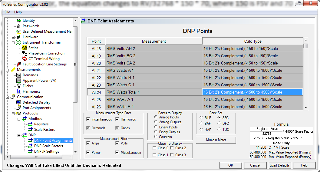
Figure 3
In the next installment in this series, we’ll deal with situations when you want the CT or VT Scale factor to be different from the corresponding CT or VT Ratio.
DNP Scaling, Part 2:
Exceptional Cases, where you might prefer to choose a Scale Factor that’s different from the CT and VT ratios.
There are two main reasons to select a Scale Factor for DNP that is different from the CT ratio or VT ratio settings, and one consequence to bear in mind when you do so. The reasons:
1. To increase the range of the analog scale.
2. To improve the analog resolution of the integer used by DNP.
Once you select scale factors for current and voltage, you should bear in mind the effect that change has on the scaling of measurements like power, which are dependent on both the CT and the VT scale factors.
Here’s an example where the range of the analog scale must be increased:
Suppose you have three VTs terminated in a wye-orientation producing 115V from line to neutral. That will result in about 200V from line to line. In this application, the 70 Series IED can be used to measure both the line-neutral voltage and the line-line voltage. But in SCADA, using a scale where the DNP integer 32,768 corresponds to 150V (or 150V * VT Ratio, in primary engineering units) you would expect to see 115V produce a DNP integer of about 25,122 regardless of the VT ratio (that’s 32,768 * 115 / 150). The problem occurs when you try to represent the line-line voltage on the same scale. That is, if 150V is 32,768, then what integer corresponds to 200V? The result is an over-range condition.
In this case two approaches are possible. You could change the Calc Type in the Configurator DNP Points page so 32,768 corresponds to a higher voltage than 150, or you could keep the same Calc Type and select a VT Scale Factor that changes the equation used by the IED to determine the DNP integer in the first place.
To increase the range of the analog scale:
In the 70 Series Configurator program, on the DNP Points page (see Figure 4, below) the Calc Type for each point can be selected from a pull-down menu. The pull-down menu for most points offers several options for the definition of the full scale. In Figure 4, the line-neutral voltage points are defined to have the default 150V full scale. The three line-line voltages have been changed so the full scale is 600V. So when points AI:3, AI:4, and AI:5 in Figure 4 are read by the RTU, now the DNP integer will be scaled in such a way that 32,768 corresponds to 600V at the terminals of the IED (or 600V * VT Ratio, in primary engineering units). In the example above, now you would expect to see 200V produce a DNP integer of about 10,923 regardless of the VT ratio (that’s 32,768 * 200 / 600). As you see, this can be done without making the VT Scale Factor different from the VT Ratio, and without having any impact on the scaling of the line-neutral voltage in AI:0, AI:1 and AI:2 or on any other measurement made by the IED. The only down-side is that the resolution is reduced somewhat. That’s because, in this application the voltage is unlikely to ever go very much higher than 200V, so the finest resolution that can be represented by DNP for line-line voltage is no longer 1 count out of 32,768. It is now closer to 1 count out of about 11,000. Practically, that is still pretty good so it may very well be the preferred approach in many if not all circumstances.
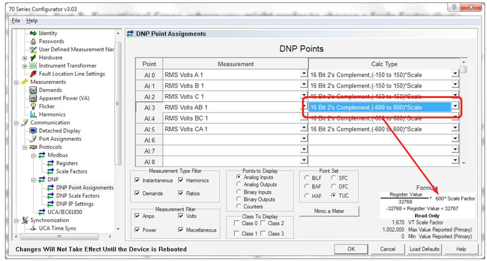
Figure 4
The objective of the second approach is to represent voltage greater than 150V at the terminals of the IED with the maximum possible resolution. That can be done by selecting a VT Scale Factor that is larger than the VT Ratio setting. By doing that, you change the equation used by the IED to determine what DNP integer results from the voltage that appears at the terminals. Here’s an example:
Suppose, you expect to see 200V line-line at the terminals, as in the preceding example. Start by setting the maximum voltage you ever expect to be able to read with SCADA equal to the DNP integer 32,768. With some knowledge of the system you ought to be able to come up with a reasonable estimate. Say the line-neutral voltage it typically 115V, but that’s regulated, so you know it never exceeds 130V. Then the line-line voltage would be 225V when the line-neutral voltage is 130V. So you might feel safe letting 230V correspond to 32,768 in DNP. Now use the equation introduced in part 1 of this article to calculate what the scale factor needs to be to make 230V produce 32,768 counts:
In Part 1 of this article, we established the basic scaling equation as: PEU = RV/32,768 * FSV * SF
Where:
- PEU is the primary engineering units (PEU is the voltage at the meter terminals times the VT ratio).
- RV is the raw DNP integer value (32,768 in this case).
- FSV defines the full scale value of the parameter being measured in secondary units (150V in this case).
- SF is the scaling factor.
Recognizing that primary engineering units (PEU) is just the voltage at the terminals times the VT Ratio setting, the equation becomes: VTR * V = RV/32,768 * FSV * SF (where V is the voltage at the terminals and VTR is the VT Ratio). Solving that equation for SF, where all the other values are known gives:
SF = VTR * (32,768 * V) / (RV * FSV)
= VTR * (32,768 * 230) / (32,768 * 150)
= VTR * 230/150
= 2 * VTR
So, as you might expect, making the VT Scale Factor two times the VT Ratio, effectively increases the full scale voltage by a factor of 2. In other words, when the IED calculates the DNP integer, the result is half of what it would have been if the VT Scale Factor were set equal to the VT Ratio. As a result the analog range is twice as wide.
The other reason mentioned why you might want to choose a Scale Factor that’s different from the CT or VT Ratio was to improve the analog resolution of the integer produced by DNP. In other words, suppose you have a line that carries 400A at peak load, but because of requirements of the protection scheme unrelated to SCADA, these CTs happen to have a 2000:5 ratio. You have no choice but to configure the CT Ratio setting in the IED to 2000:5 (or 400:1) but if you make the CT Scale Factor setting 400 (400:1) on the DNP Scale Factors page in the Configurator, then the DNP integer 32,768 corresponds to 10A at the terminals, or 4000A primary engineering units. So your peak load of 400A only produces a DNP integer of 3,277. Essentially, your resolution has been cut by a factor of ten.
To improve the resolution, you could select a different Calc Type as shown in Figure 4 (but this time configuring the point for the Amps). Where that was probably the preferable approach for voltage, it is less advantageous for current. First, the only Calc Type available for current that is lower than the 10A scale is the 5A scale (see Figure 5). That only improves resolution by a factor of two, where we’d really prefer to get something closer to a factor of ten improvement. The other drawback of that approach is that your load actually is one tenth of what is normally expected by the IED, which was not the case in the preceding (voltage) example. As a result, the load in Watts, VARs and VA is also lower by a factor of ten than what is anticipated by the IED so the resolution of those measurements is also impacted.
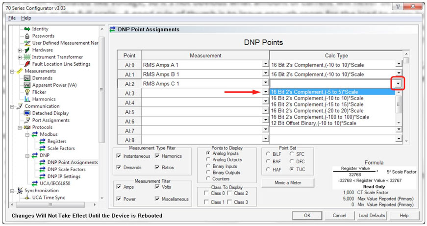
Figure 5
In this example, the preferable approach is making the CT Scale Factor smaller than the CT Ratio. Then the change in the configuration of current scaling will automatically apply to improving the resolution of the power measurements as well. So, how to choose a CT Scale Factor?
Taking the same approach as in the previous example, first you want to estimate the amount of current that you would like to produce a DNP integer of 32,768. In our example we said the peak current is about 400A. Current is not regulated like voltage, so it’s not obvious what amount of current will never be exceeded, in order to define that as the full scale. A good rule of thumb is to leave enough room for the load to grow by a factor of two over time. Meters and CTs usually do that automatically by defining a nominal full scale output at 5A, but then building a rating factor of 2 into the CT and making the meter operate through 100% over-range. In our example, the CT full scale is no help because the CT is over-sized to accommodate the relays. So we’ll take that into consideration when selecting the CT Scale Factor. OK, so the known peak load is 400A, and we’ve decided to accommodate load growth up to 800A. So we’ll make 800A correspond to a DNP integer of 32,768.
The equation we use is: PEU = RV/32,768 * FSV * SF
Where:
- PEU is the primary engineering units (PEU is 800A in this case).
- RV is the raw DNP integer value (32,768 in this case).
- FSV defines the full scale value of the parameter being measured in secondary units (10A in the typical case).
- SF is the scaling factor, which is we want to solve for.
Solving the equation for SF, where all the other values are known gives:
SF = (32,768 * PEU) / (RV * FSV)
= (32,768 * 800) / (32,768 * 10)
= 800/10
= 80
OK, so 80 is the CT Scale Factor. What does that do for me?
1. When reading Amps from the IED: In our example 400A is peak, so on a certain day maybe you’ve got a load of 250A. The CT in the station has a 2000:5 ratio, so the IED sees 0.625A at the terminals and your RTU reads 10,240 counts. SCADA should be configured to interpret that as follows:
PEU = RV/32,768 * FSV * SF
Where:
- PEU is the answer you’re looking for.
- RV is the raw DNP integer value you read from the IED (10,240 in this case).
- FSV defines the full scale value of the parameter being measured in secondary units (10A in the typical case).
- SF is the scaling factor, which we just determined should be 80.
PEU = RV/32,768 * FSV * SF
= RV/32,768 * 10 * 80
= RV/40.96 ← This is the equation you set in SCADA.
= 10,240/40.96
= 250A
2. In the beginning of Part 2 of this article we said: Once you select scale factors for current and voltage, you should bear in mind the effect that change has on the scaling of measurements like power, which is dependent on both the CT and the VT scale factors. So then what impact do the scaling factors we chose have on reading the Power?
Using the examples we’ve worked so far, let’s look at the big picture:
In the first example, we decided that we could make the VT Scale Factor be 2 times the VT Ratio in order to see the line-line voltage without over-ranging in DNP. But we also established that it would probably be preferable not to monkey with the Scale Factor if we could just choose a different Calc Type. We didn’t say what the VT Ratio was. Let’s say that’s 70:1 and since the VT Scale Factor will be the same as the VT ratio, the Scale Factor is 70 also but we’ll use a Calc Type that defines the full scale line-line voltage as 600V.
In the second example, we decided to make the CT Scale factor 80 even though the CT Ratio is 400 (2000:5 = 400:1) to improve the resolution of the current where the load is actually less than the typical load anticipated by the IED.
So the settings on the IED are this:
VT Ratio 70:1 VT Scale Factor 70
CT Ratio 2000:5 CT Scale Factor 80
Let’s say the system voltage is 13.8kV line-line, and the load is 350A. For the purposes of this example, we’ll let the system be balanced and the power factor be unity (if Watts = VA and VARs = 0 we can work just one example instead of three because the formulas for scaling P, Q, and S in DNP are identical.) That makes P = 8.366MW. The IED is producing the following integers: For line-line voltage: 10767, for line-neutral voltage: 24864, for current: 14336, and for three-phase total power: 10878 counts. The question at hand is how should SCADA be set up to interpret all of these measurements in Primary Engineering Units?
The equation we’ve been using all along is still appropriate for all these cases:
PEU = RV/32,768 * FSV * SF
Where PEU is the answer, and RV is the integer we read from the IED in DNP. The only trick is to recognize which value to use for FSV and SF based on the settings that we chose. This is where the Configurator program comes in very handy. See Figure 6. When you click on a DNP Point in the point list, the formula in the lower right-hand side updates to give you exactly the right values for the Full Scale Value (FSV) and the Scaling Factor (SF) that the IED is configured for. So we’ll just use those:
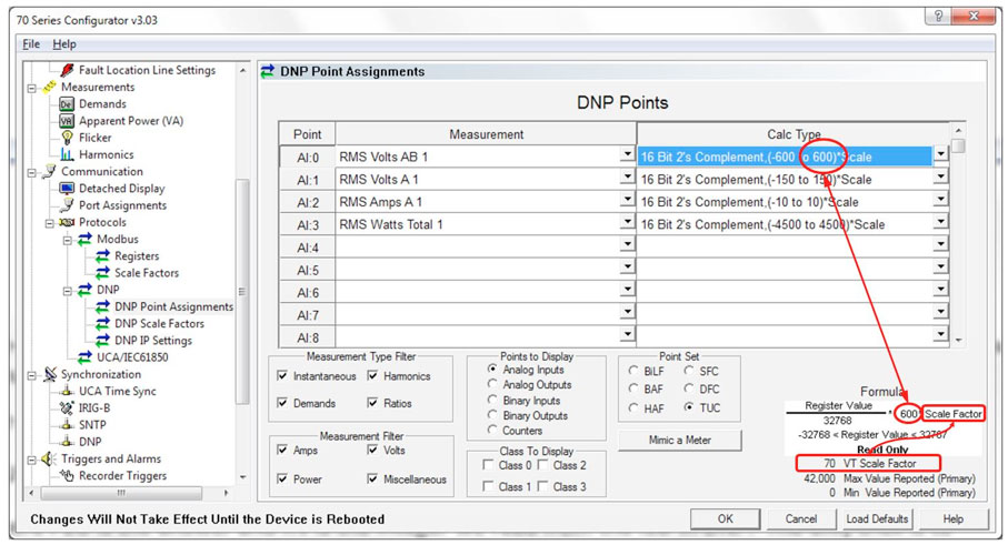
Figure 6
Figure 6 indicates, for line-line volts, FSV = 600 and SF = 70. So we have:
PEU = RV/32,768 * 600 * 70
= RV * 1.2817
= 10767 * 1.2817
= 13,800V
To get the results in units of kV, the equation RV * 1.2817 in SCADA becomes RV * 1.2817 / 1000 or RV * 0.0012817, which is the same as the following equation:
In SCADA: VLL = RV/780.2
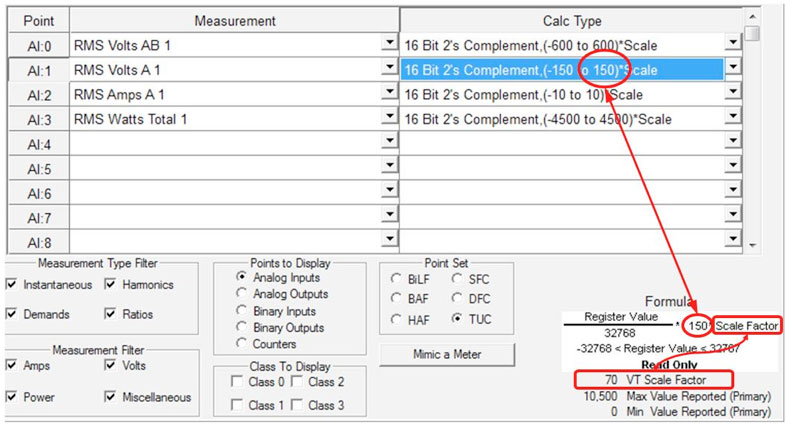
Figure 7
Figure 7 indicates, for line-neutral volts, FSV = 150 and SF = 70. So we have:
PEU = RV/32,768 * 150 * 70
= RV * 0.3204
= 24864 * 0.3204
= 7,967V
To get the results in units of kV, the equation RV * 0.3204 in SCADA becomes RV * 0.3204 / 1000 or RV * 0.0003204, which is the same as: VLN = RV/3120.8 which is what we use for SCADA.
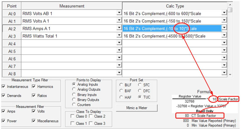
Figure 8
Figure 8 indicates, for current, FSV = 10 and SF = 80. So we have:
PEU = RV/32,768 * 10 * 80
= RV * 0.024414
= RV / 40.96 ← This is the equation you set in SCADA.
= 14336 / 40.96
= 350A
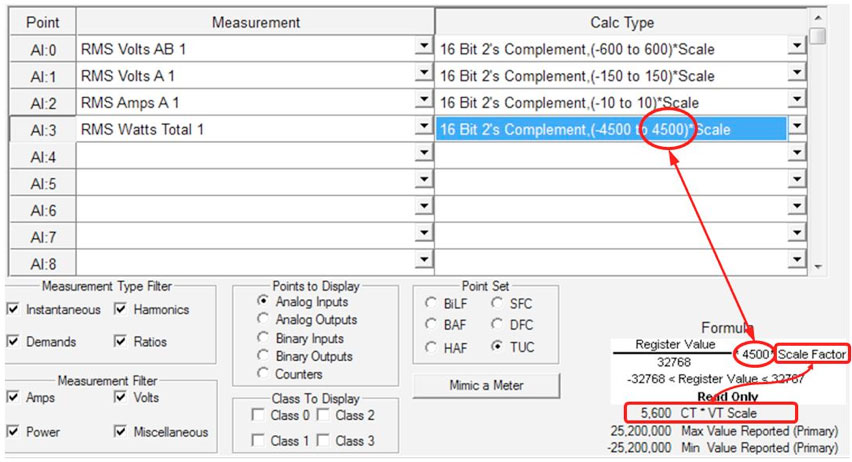
Figure 9
Figure 9 indicates that, for power, FSV = 4500 and the Scale Factor is the CT Scale Factor times the VT Scale Factor, so SF = 70 * 80 = 5600.
PEU = RV/32,768 * 4500 * 5600
= RV * 769.043
We’ll go ahead and divide 769.043 by 1,000,000 so the result comes out in MW instead of watts.
= RV / 1300.3
= 10878 / 1300.3
= 8.366MW
DNP Scaling, Part 3:
Exceptional Cases, where a Scale Factor is not necessary.
This topic is relatively straight forward compared to the previous two topics. Essentially, there are some measurements where the magnitude is not a function of the CT and VT scaling. Some examples include:
- Power Factor always varies from -1 to +1 regardless of current and voltage magnitude.
- Values expressed as a percentage, such as %THD range only from 0 to 1.
- Phase angles magnitude, generally ranges from -180 to +180 degrees.
- Frequency is not dependent on voltage or current magnitude and is generally regulated so tightly around either 60 Hz or 50 Hz, that maximum resolution can be achieved by using an offset equation to convert from DNP counts to Primary Engineering Units.
- Any value whose content represents “packed bits” (such as the IED’s self diagnostic, or Health, point) is obviously is not scaled. Each bit represents a different binary condition. A look-up table is required to determine the meaning of each bit once the point has been parsed.
- Energy in the 70 Series IED is generally represented as an unsigned 32 bit integer without scaling, and expressed in units of kWh. The energy registers generally roll over at 4,294,967,295 (i.e. 232) kWh. Scaling is only required if you prefer to read energy in units of MWh, in which case scaling is just divide-by-1000, and then the register rolls over at 4,294,967.295MWh. (For what it’s worth, that’s roughly 245 years running continuously at 2,000MW.)
In each of the above cases the scaling is usually simply divide-by-10, divide-by-100, or 1000. Are all indicated in the Configurator program when the Point List is configured (see Figure 10) and also described in the Users’ Guide for DNP Protocol implementation on the 70 Series IED, Bitronics document ML0026, a copy of which is included on the Utilities Software CD that comes with the IED, and also available for download from the NovaTech Automation website.
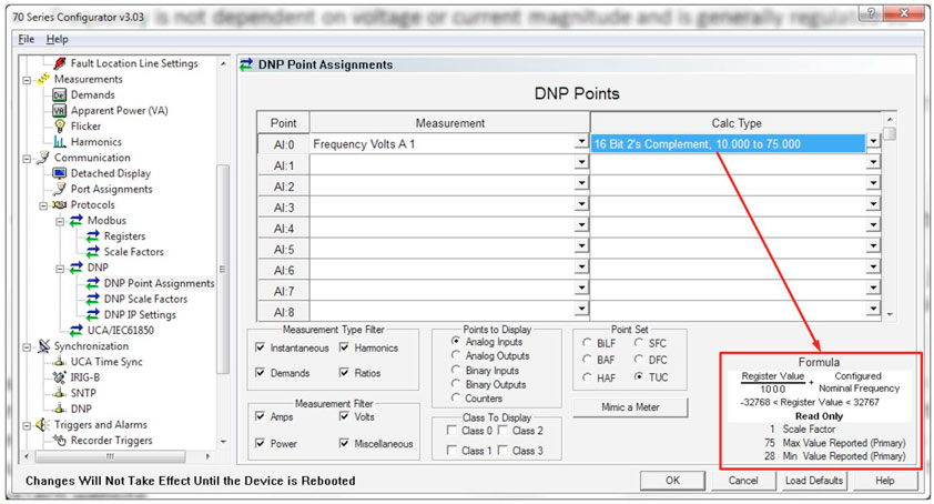
Figure 10
Figure 10, above, illustrates the offset-proportion scaling used for frequency. See how the Register Value only encodes the deviation of the frequency from nominal (60 or 50Hz). So, for example 59.975Hz would be encoded as the DNP integer -25 counts. The RTU should divide -25 by 1000 and add that to 60 (we hopeyou never see 59.975 Hz in a 50 Hz nominal system). So 60 – 0.025 = 59.975. This method produces sufficient resolution to represent frequency to +/- 1mHz.
DNP Scaling, Part 4:
Binary math primer, the significance of “Two’s Complement”.
We occasionally get asked why SCADA might report a measurement from an IED where the integer is greater than 32,768. So I thought it might be interesting to review a couple fundamentals of binary math inasmuch as they apply to SCADA.
In the most fundamental form of binary math, you’ve only got ones and zeros; no minus sign is available. Negative numbers are often represented by making the most significant digit a one. Let’s use four-bit binary for examples because 16-bit is a little tedious. Insigned binary you can count from zero (0000) up to seven (0111) but if you make the left-most digit a one (1000) that makes it a negative number, not a larger positive number. That’s by convention of course; it doesn’t have to be that way. If you never expect to need to represent a negative number, then there’s nothing wrong with saying 1000 is binary 8, and continue counting up to fifteen (1111).
So the first thing we need to establish is that most RTUs need to be configured to recognize which binary numbering convention they are using. An unsigned sixteen-bit integer is not the same as a sixteen-bit-two’s-complement integer. If an IED is using two’s complement encoding, which is a form of signed binary, then the highest positive number it can see is a zero followed by fifteen ones. In decimal form, that is: 0 x 215 + 1 x 214 + … + 1 x 21 + 1 x 20 = 32,767.
Now. It is possible to define a system where the left-most digit (most significant digit) is just the sign, so 0001 = 1 and 1001 = -1. But computers generally don’t use that kind of system because you’d like to see a positive number and a negative number of the same magnitude add up to zero. The system just described doesn’t support that because 0001 + 1001 = 1010, which would be -2, not zero.
This is where the “two’s complement” convention comes into play. Suppose we define a convention where, in order to make a positive binary number negative, we invert all the digits then add one. It sounds kind of arbitrary, but see how it works: If 5 is 0101, then in order to make -5, inverting all the digits produces 1010, then adding a one results in 1010 + 0001 = 1011. Hence, -5 is 1011. So adding +5 to -5 should result in 0 as follows: 0101 + 1011 = 0000, which is true given that we are only considering four bits in this example. In this convention, any number whose most significant digit is a 1 is a negative number. For example:
10002 = -810
10012 = -710
10102 = -610
10112 = -510
11002 = -410
…and so forth.
Now, obviously, if an RTU were not configured to recognize that the numbers used in the example above are encoded according to the two’s complement convention, then the RTU would not interpret 1011 as negative five, it would interpret 1011 as positive eleven. Just as eleven should not be possible in four-bit-two’s complement (because 01112 = 710 is the highest number that’s possible without the most significant digit becoming a 1). This is analogous to the situation when the RTU returns a number between 32,768 and 65,535. You don’t expect it to be possible for a number to be greater than 32,767. All numbers in the range from 32,768 to 65,535 have 1 as their most significant digit, so those should all be interpreted by SCADA as negative numbers. That is usually just a setting that needs to be made when setting the system up.